Apart from making things that decorate your place’s aesthetics, 3D printing technology is majorly used for creating objects that are actually functional.
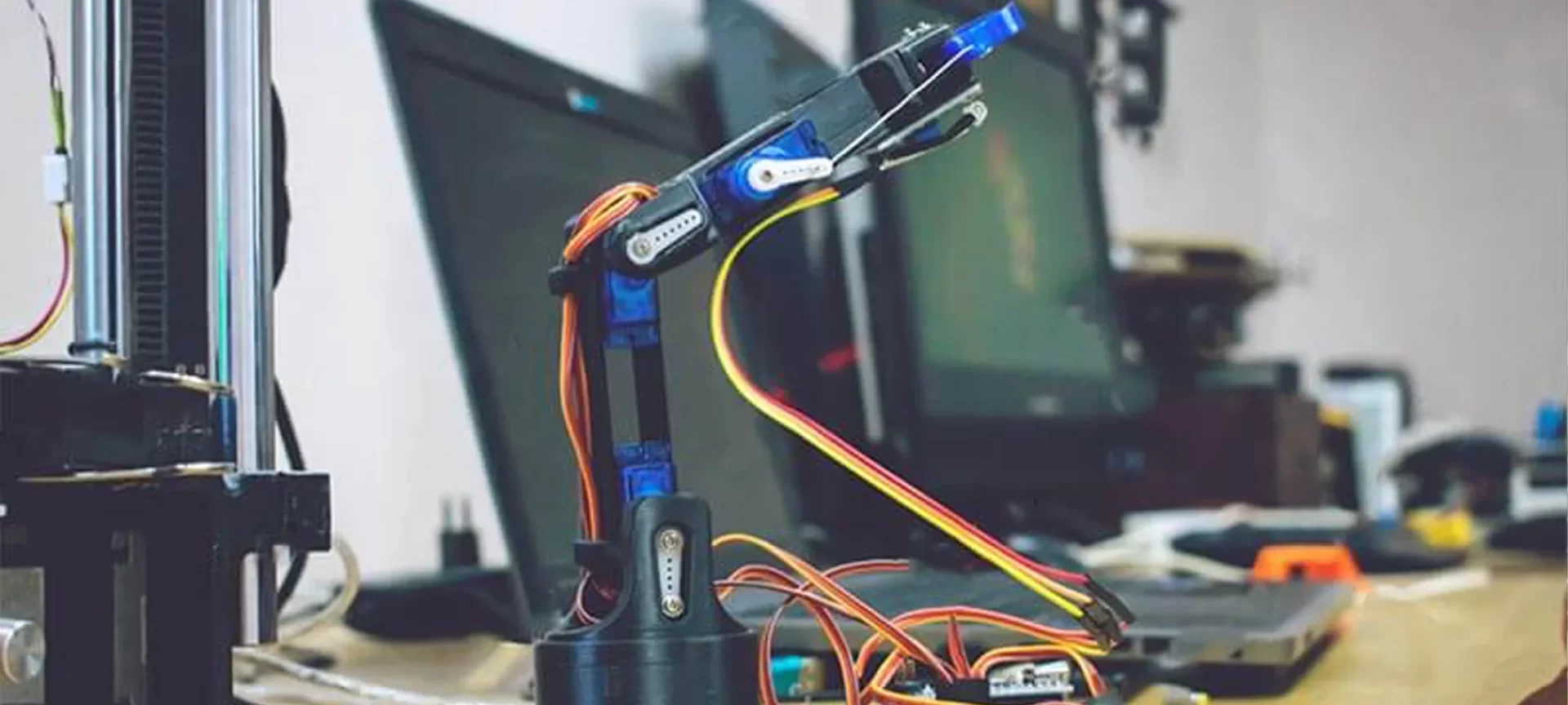
From vases to lightweight and strong parts needed for aerospace applications, there is a lot one can create using AM technology. And, one such example is the 3D-printed robotic arm.
If it seems interesting to you too, how about printing one by yourself? Let’s find out the stepwise procedure for creating a 3D printed robotic arm.
How to Make a 3D Printed Robotic Arm?
Before getting to the stepwise procedure of making this part, let’s go through the essentials without which making the part is impossible. Here is a list of things you would need before starting this fascinating project.
- An Arduino Uno
- Four Standard Servo motors
- Two Micro Servers
- Eight Momentary Push Buttons
- An On/Off Switch
- A Potentiometer and knob
- A Green LED
- A Printed Circuit Board
- Eight Resistors of 10K Ohm
- A Resistor of 220 Ohm
- Wires and Connectors
- An Afinia 3D printer
- One kilogram roll of PLA filament
- A power supply capable of withstanding 2 Amperes current.
Having gone through the hardware required for a 3D printed robotic arm, it’s time to know what you are going to need in terms of the software.
As you know, for 3D printing any part you need a 3D design file. The same applies to a robotic arm. Although there might be plenty of 3D design files available for making components of 3D printed robots, the one that we are discussing is based on the 3D design file present on Instructables. The best part is that the files are available for free.
So, once you are done collecting the mentioned hardware along with the needed software files, you are all set to go with the first step in the creation of a 3D printed robotic arm.
Step 1: Printing the Components
The 3D files available for download from Instructables are for making components that easily fit on the Afinia H479 printer. The complete arm is 20 inches long and takes a lot of time as well as material to be 3D printed.
It is recommended to use a resolution of 0.25 mm and a hollow-fill for making all the parts. Moreover, you might need a raft for helping the part to adhere to the print platform and help the printer do the needful for an unlevelled table.
It takes about 32.5 hours to build this part. This includes building the raft material and utilizing 842.8 grams of filament thereby meaning that the part can be printed using a kilogram weighing filament spool.
Although most of the parts have flat sides facing the platform, many of them also have delicate tabs to hold the cables. So, take proper care while removing the draft as well as support material.
Step 2: Coding the Arduino and Extending the Servo Cables
When waiting for the parts to be printed, start working on uploading the code and soldering the electronics. The code of controlling the servo motors is very easy to use. The control of joints and gripper servos is via a pair of buttons that increase or decrease the servos’ positions by a step.
The base of it is connected to a potentiometer mapped to its rotation and depending on the order in which you wire your buttons, you might need to adjust the pin numbers in the code.
It is recommended that you test the code with the servos to ensure that their limits are consistent with the ones that are defined in the code. Because testing these after the arm is assembled could either damage or break it.
Also, note that the same physical setup can be used with different coding in case you desire to have your arm do simple automated tasks.
The servos will be positioned at numerous points along the arm, so the cables have to be extended. For doing so, simply cut the cable and solder in an extension present between the servo and the connector.
Position the first servo at the base, the other two at the lower joint extended 5 inches from the base one. Then position one at the middle joint, exactly 10 inches away from the previous one. The one at the upper joint is 15 inches away from the one at the middle joint. And finally, one at the gripper exactly extended 18 inches away.
Step 3: Making More Cables and Building the Circuit Board
To connect the circuit board to the Arduino, make two sets of cables: the servo signal cable and the button signal cable. The former has male headers at both ends, each with six pins, whereas the latter has 8 pins each. Additionally, one end separates two of the pins from the other six while they are plugged in on the opposite side of the Arduino.
To efficiently route the wires and signal use the circuit board arm. It is advised to start with the resistors and then with various connectors, finally soldering the connections.
Step 4: Building the Gripper and the Lower Segment
After having the parts at your disposal, you can start the assembling procedure. Commence by pushing the micro servo into the gripper base and route the cable through the channel. Thereby, attach the 4-prong horn to it and rotate the same to the point where you want the most open position for the gripper.
Push on the claws and the other micro servo, ensuring the gears mesh and assembling the rest of the gripper respectively.
To build the lower segment of the arm, match the long parts by their cable channels and push them together. Snap-in the 4-prong servo horns, making certain that they are pushed completely backward. Then bolt the servo over its mount, check its bulk on the interior of the arm segment. Connect both the halves of the lower segment with each other using the small braces
Step 5: Building the Middle Segment and Routing the Cables
The middle segments’ long side can be assembled in the same way as the lower segment. Rotate the upper joint’s micro servo on the gripper to either one of its limits. Then push it into the micro servo horn, while keeping the parts at approximately 90 degrees.
Doing the same with the middle joint servo will align the servos in a way that their limits are symmetrical and their joints have a considerable range of motion. It is also advisable to attach the braces to one side of the middle segment for stability.
For routing, the cables start from the still-open side of the middle segment, gently keep on pushing the cables into their channels and under the tabs. This is to ensure that there is enough slack for moving joints, rotating the part so that the cable is as far from the channel as much as it can be.
Keep on routing the cables even more after carefully removing the braces if needed for reaching the clips. In case you are using a tool to assist clipping the cables, be careful to not pinch or accidentally cutting the wires.
Step 6: Attaching the Arm to the Base and then Building it
Attach a standard servo to a servo mount, then place both mounts in a standard rotating base. Thereafter place the top two bolts for the second servo in the mount without adding the servo.
The next step is to rotate the mounted servo in a manner that it reaches at one of its limits and gently sliding in the arm and pressing the servo horn. Then, push the other servo into the other horn, secure it by the remaining bolts and thread the servo cables through the holes in the rotating base.
To start building it, push the final servo into the bottom of the rotating base and sandwich the top of the base between the two halves of the rotating base, thereby snapping both the halves together. Check whether the arm is able to rotate when being constrained by the base. Once done, mount the last servo to the bottom of the base.
Ensure it is facing the correct direction and then rotate it to one of its limits, even more rotate the arm to match, keeping an eye on the cables. Last step for building the arm to the base is pushing the top of the base to bottom, thereafter meshing the teeth and the servo/horn. Note that the indication of arm rotation is the noise that’s heard by the base servo that’s rotating with it.
Step 7: Making the Control Panel and Adding the Circuit
The control panel consists of eight buttons, a potentiometer, an LED, and an on/off switch. The buttons and potentiometer can be bolted around the base if they are threaded. Also, it is easy to solder leads to almost all the parts before attaching them to the base of the part. Also, it is recommended to add a 220 Ohm resistor to the end of the LED’s positive lead.
Note that, the LED as well as the on/off switch press-fit into the base. After all of these parts are inserted, attach the knob to the potentiometer. The step is to bundle some wires together. Powdered from one pin on the circuit board to the other will be the 5 Volts power lines that stem out from the button. The last step of making the control panel is to solder the 8 signal lines with a male connector. For doing which you can use a logical order for keeping a track of identifying the button properly.
To the circuits all you need to do is simply start plugging the cables from the control panel to the circuit. Remember that the header goes into the row of female connectors just beneath the resistors. Whereas, the 5 Volts from the potentiometer and the buttons go to the 5 Volts headers. And the ground from the potentiometer, the LED, and the black wire goes into the GND headers.
Step 8: Plugging in the Arduino, Servos, and Closing the Base
Make use of the cables that you made earlier for plugging in the Arduino. While doing so make sure that the buttons go to the pins numbered 2-7 and A3, A4 whereas the servos signals go to the pins numbered from 8-13.
While the power for LED goes to the 3.3 Volts pin as well as the wiper of the potentiometer goes to pin A0. Note that, the plugs from the servos go into the male headers present at the top of the circuit board.
After doing so, test the code, check the servos, if needed update the code. Lastly, flatten the electronics as much as you can, and push the control panel onto its matching bottom part, then close the two halves.
Finally, grab the power supply to start making use of the newly devised robotic arm. If you feel the need to add a different gripper or changing the code for autonomous tasks, do so after the arm starts working.
The Conclusion
There are many areas of application of a 3D printed robotic arm. It’s a high-tech tool that is analogous to the human hand. Its area of application depends mainly on the type of program that’s fed into it. In case you have made it for your home, it can be used for helping you out in holding various things precisely and transferring them to the desired location.
Things of micro-size like screws, bolts, nuts, etc can be lifted by the 3D printed robotic arm and can be fitted into locations wherein it’s hard for a human hand to work. Customized versions of the part are mostly used in mechanical labs for carrying out various jobs which are difficult to do with a human hand.